It took us five months of intensive work to assemble FF-2B with its new beryllium electrodes. The safety requirements of dealing with beryllium to ensure that none of us were exposed to beryllium dust was one safety concern that slowed us down. But in the process, we have succeeded in greatly upgrading our experimental device. Here’s a summary of what we did.
January: Dr. Hassan installed the glove box used to isolate all beryllium parts and for work with decaborane fuel.
February: We did a preliminary bake-out of the silicone gaskets and O-ring and Viton gaskets in a special vacuum oven. This was essential to get rid of volatiles that needed higher temperatures for bake-out, 190 C, than the Mylar insulators on our device could withstand. Also, it allowed us to bake out rapidly with all surfaces exposed.
At the same time, using the glove box, we assembled the beryllium anode onto the steel plate that attached it to the rest of the device. To get high electric conductivity, we use indium, a soft metal, between the silver-coated steel plate and the beryllium. But when we tried to do this, we found that we needed to first remove the very thin layer of beryllium oxide, an insulator that forms on the beryllium when it is in air. For this we needed an ultrasonic welder, which uses ultrasound to break up the oxide layer, trapping the oxide particles under the molten indium. The working surface had to be heated to about 100 C to make sure the indium melted quickly. It took a while to get the hang of this new technique, but once we got it, we were able to successfully merge the anode and its plate. Then we mounted the anode onto the device.

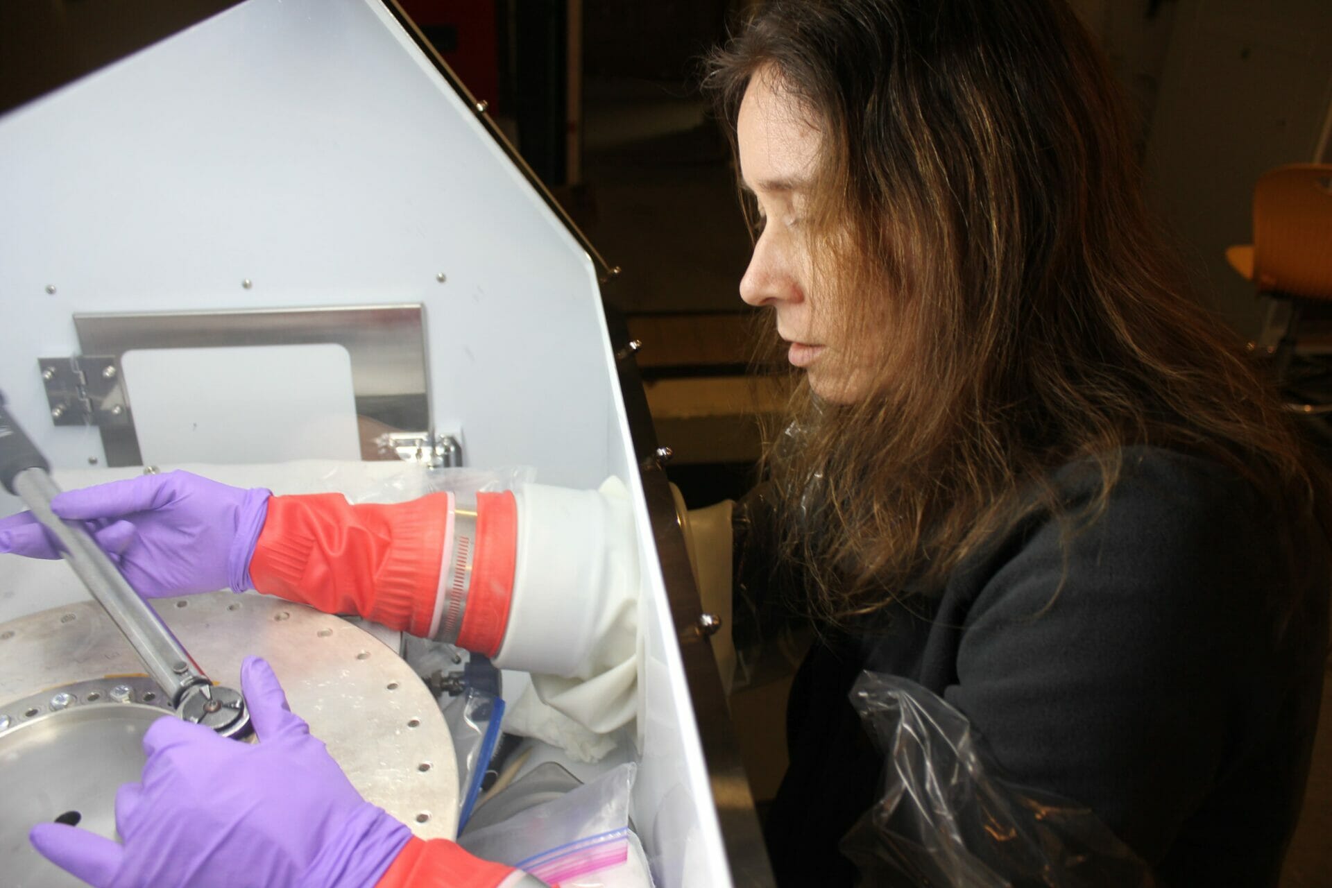
Figure 5. Ivy Karamitsos tightens the bolts connecting the bottom of the beryllium anode (grey disk) to its connecting steel plate. She’s protected from any potential contact with beryllium dust by the sealed glove box. The Plexiglass window to the box, barely visible in this photo, is at the border of the white area. Four layers of gloves—of which three are visible—protect against any possible tears. We did not actually believe that we produced any beryllium dust in these operations, but have used the highest possible protections in any case.
March: Dr. Hassan added a new upper vacuum chamber on top of the anode. This chamber is designed to observe the electron beam, which is generated by the plasmoid and exits through a hole in the new beryllium anode. Next, we used a steel brace to bolt the cathode onto its steel plate. That went faster, with our experience from the anode. But then we had to carefully center the cathode onto the anode. This is always a difficult operation, as we are aiming to get centering within about 50 microns. This is needed, because the gap between the cathode and the insulator, which lies between the anode and cathode, is only 500 microns, a half-millimeter, and we want the gap to be even within about 10%. Our IT team, systems administrator Jose Varela and CIO Karamitsos completed custom software, FetchScopes, that fetches the data from our old, used, oscilloscopes to our data computer without having to rely on no longer supported drivers or on ancient Windows software. Also, putting on the space (bunny) suit proved to be somewhat challenging for some of us.

Figure 6. The new upper vacuum chamber installed on top of the anode. The chamber is being used to measure the electron beam, exiting through a hole in the anode.


Figure 7. Karamitsos (top) holds the beryllium cathode in one hand inside the glove box, demonstrating its light 3-kilogram weight. The tungsten cathode it replaces weighed 30 kg. Lerner (bottom) completes lowering the cathode and its steel brace onto the silver-coated steel connecting plate.
We then added the new main vacuum chamber, which has enlarged windows, and sealed it up. In the process, we made a disturbing discovery. Despite many checks of the drawings, the beryllium cathode had 8 fewer bolt-holes than the vacuum chamber that bolted on to it. Fortunately this did not really matter, as the bolts in the holes they had in common applied enough pressure to seal the Viton gaskets. But the fact that a potentially serious error had gone unnoticed had our CIO Karamitsos insisting on generating a complete 3D assembly drawing for the whole device, a task undertaken by LPPFusion Mechanical Engineer Rudy Fritsch. Once the drawing is complete, in the near future, new drawings can automatically be checked by Solid Works software ($10K+ additional module not purchased yet.)

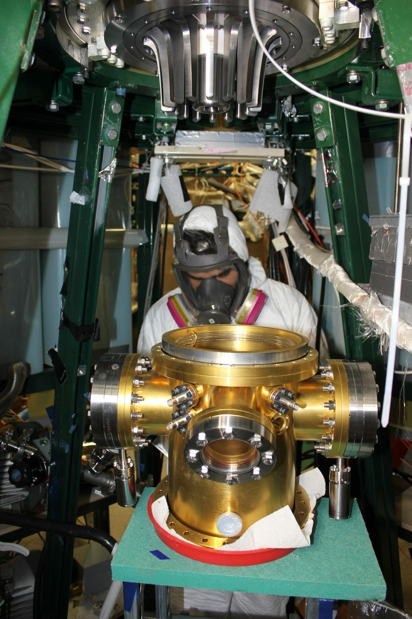
Figure 8. Dr. Hassan, in full protective dress, prepares to install the new vacuum chamber onto the beryllium electrodes, which are already attached to the device. The gold color of the chamber is from its titanium nitride coating, which prevents oxygen from escaping the underlying stainless steel.

Figure 9. The beryllium electrodes, with the anode (with hole in center), white insulator, and cathode all centered to within 50 microns, viewed from below.
April: This month was devoted to upgrading the vacuum system to have all remote-operated valves. This would be important in the event of any break in the vacuum, but also is essential when we start firing with decaborane. We expect a side reaction will produce small amounts of radioactive carbon-11, with a half-life of 20 minutes. We will have to stay out of the experimental room while firing, but the C-11 will decay to background levels overnight. We had to take a lot of time to get rid of all leaks, including replacing outdated valves.
May: During this month we baked out the entire chamber at 100C. We needed to add insulation, surrounded by aluminum foil to get everything hot enough to eliminate as much water, remaining volatiles and especially any trapped air as possible. Only oxygen reacts with beryllium at room temperature, so that is what we wanted most to get rid of. We succeeded in meeting our goal of less than 0.2 microtorr of oxygen per minute entering the chamber.

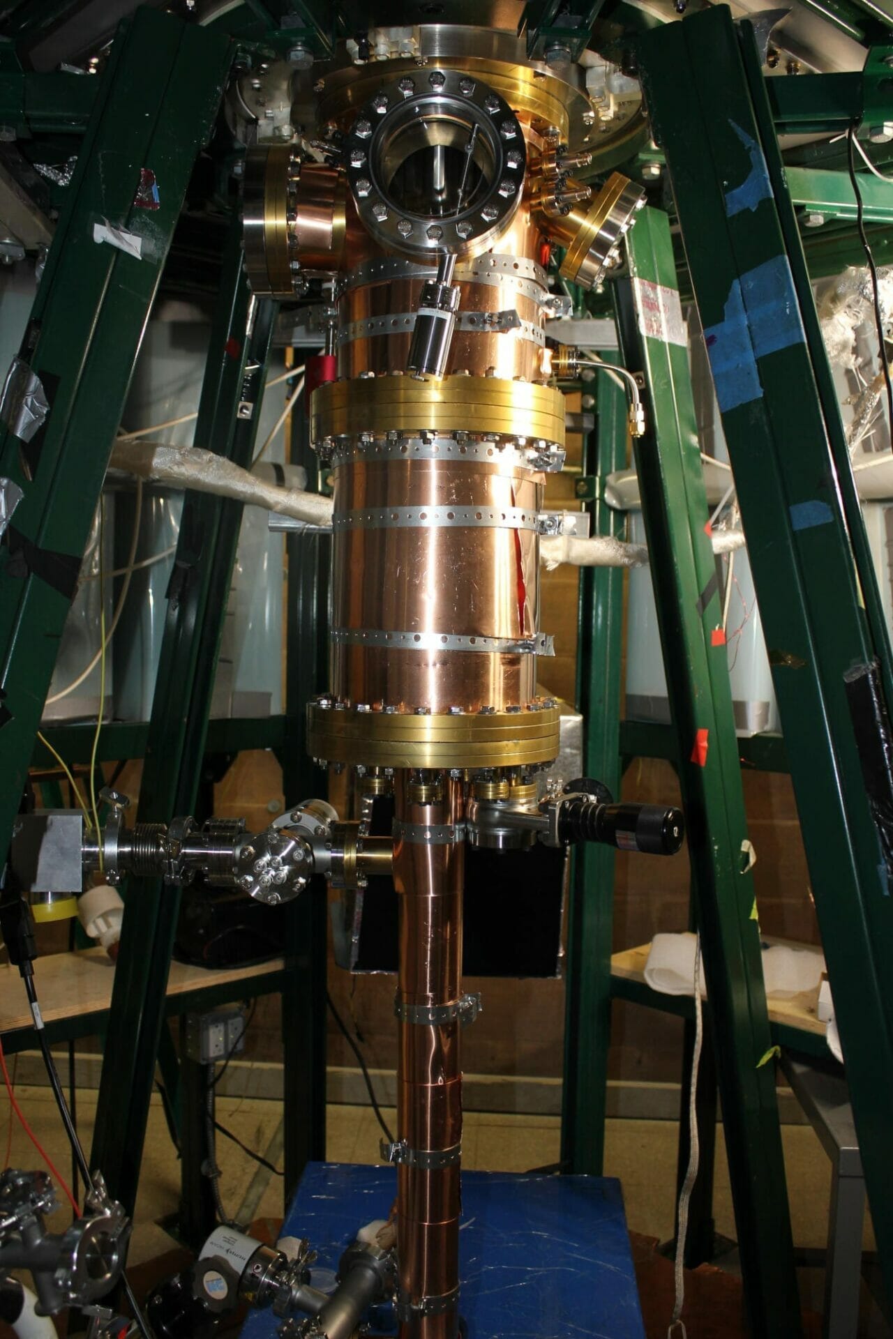
Figure 10. The vacuum chamber and drift tube (thin tube below) get copper sheet cladding to spread the heat out evenly during bake-out.
While all these preparations were going on, we also used the glove box to take a 2-gm sample of our new decaborane fuel for testing. The tests went very well with only 0.068% B-10 and 0.0007 % iron present. This means we will be able to use the fuel late in the year without worrying about the production of radioactive Beryllium-7 from B-10 or any significant chemical impurities.
Outside of the lab the team produced a video regarding Lerner’s take on “black hole” M87. Lerner was invited by NJ senator Joe Pennacchio to present the latest on fusion energy R&D with other fusion researchers at a Fusion Symposium in Trenton NJ. Lerner also presented at NYC MENSA why fusion energy is the missing link necessary for the Green New Deal.

Figure 11. The FF-2B vacuum chamber with insulation and outer aluminum foil. Now it looks like a baked potato, but getting the bake-out done is more important than looks!
